#Arduino GPS Program
Explore tagged Tumblr posts
Visit Tumblr Blog
Explore Tumblr blogs with no restrictions, modern design and the best experience.
Last Seen Tumblr Blogs


Fun Fact
Tumblr has been providing a Korean-language service since 2013.
Text
Top success stories emerging from Atal Tinkering Labs
Atal Tinkering Labs (ATLs), an initiative by the Government of India under the Atal Innovation Mission, have transformed the educational landscape by fostering innovation and creativity among school students. These labs, equipped with state-of-the-art tools and technologies, empower young minds to explore, experiment, and innovate. Over the years, several inspiring success stories have emerged from these labs, showcasing the potential of young innovators to solve real-world problems. Let’s explore some of the most outstanding innovations:
1. Affordable Braille Printer by a Teen Innovator
A young student from an ATL in Maharashtra developed an affordable Braille printer using simple, cost-effective materials. Inspired by the challenges faced by visually impaired individuals in accessing printed content, the innovator utilized 3D printing and Arduino programming to create a solution that costs a fraction of traditional Braille printers. This project not only garnered national recognition but also opened avenues for mass production and accessibility.
2. Water Purification System by Rural Students
In a small village in Rajasthan, students from an ATL tackled the problem of contaminated drinking water. Using basic science and technology, they created a portable water purification system powered by solar energy. Their innovative approach combined affordability with sustainability, making clean drinking water accessible to their community. This project has been lauded as a model for addressing rural challenges through STEM.
3. IoT-Enabled Smart Farming Solution
A team of students from an ATL in Punjab developed an IoT-based smart farming system to assist local farmers. The system monitors soil moisture, temperature, and humidity, providing real-time data to optimize irrigation and crop yield. By integrating mobile alerts, the project offered a user-friendly solution for resource optimization, earning accolades at various innovation fairs.
4. Low-Cost Prosthetic Arm
A high school student from an ATL in Karnataka designed a low-cost prosthetic arm using 3D printing and robotics. The prosthetic was aimed at helping underprivileged individuals who couldn’t afford expensive medical solutions. With a focus on functionality and affordability, this project showcased how young minds could bridge the gap between technology and societal needs.
5. Traffic Management App
Students from an ATL in Delhi created a traffic management app to tackle congestion in their city. By using GPS and data analytics, the app provided real-time traffic updates and suggested alternative routes. This project highlighted the potential of technology in solving urban challenges and was appreciated by local authorities.
Why ATLs Matter
The success stories from Atal Tinkering Labs underline the importance of early exposure to STEM (Science, Technology, Engineering, and Mathematics) education. These labs cultivate critical thinking, problem-solving skills, and creativity, enabling students to become future-ready innovators. They also emphasize the power of collaborative learning, as students work together to tackle pressing issues.
Join the innovation movement
Atal Tinkering Labs have become breeding grounds for young innovators who dare to dream big and take action. From addressing social challenges to creating cutting-edge technologies, these students are shaping a brighter, more sustainable future. Join Us Today! As we honor these achievements, let’s keep encouraging and empowering the next generation of innovators and leaders. Who knows? The next big innovation might just come from an ATL near you!
Are you inspired by these stories? Encourage the young learners around you to explore STEM opportunities. Share this blog and help spread the spirit of innovation! Call us today to discover how our programs can help unlock the potential in young minds and ignite their passion for learning!
0 notes
Text
Robotic Invention Ideas
Robotics has completely changed industries around the world, spurring innovation in everything from agriculture to healthcare. Ideas for robotics inventions lead to countless opportunities, enabling developers to create solutions that solve practical issues and boost productivity.
Personal Assistant Robots
Imagine a robot that can make your coffee in the morning, remind you of critical duties, and handle your daily schedule with ease. Robotic personal assistants are growing in popularity because they can help with household management, senior care, and busy professionals. Voice recognition, artificial intelligence (AI), and Internet of Things (IoT) technology can all be combined by inventors to produce a very customized and engaging experience.
Autonomous Delivery Robots
Autonomous delivery robots offer a novel approach to effective and frictionless distribution in light of the growth of e-commerce and online meal delivery. With GPS systems, obstacle recognition, and temperature-controlled compartments to guarantee the safe delivery of goods or meals, these robots can maneuver through streets or offices.
Agricultural Robotics
Significant progress has been made in agricultural robotics, which has helped to solve the labor crisis and boost output. Autonomous drones for crop monitoring, robotic harvesters, and precision weeding robots are some examples of invention concepts in this field. These methods can guarantee higher yields, limit waste, and need less human labor.
Healthcare Assistance Robots
By helping with surgery, rehabilitation, and elder care, healthcare robots are revolutionizing patient care. An AI-powered diagnostic bot, a surgical robot with precise movements, and a robot made to assist patients with mobility issues are examples of robotic inventions in this field. These innovations can provide high-quality care while reducing the workload for medical personnel.
Educational Robots for Kids
Children are increasingly being taught STEM (science, technology, engineering, and mathematics) principles through the use of educational robots. Interactive bots that gamify education, AI-powered tutors for individualized learning, and programmable kits that let children construct and program their own robots are some examples of educational robot concepts.
Tips for Turning Robotic Ideas into Reality
Research is the first step. Learn about the needs of your target audience and look into current technology to find any holes that can be filled.
Learn the Basics of Robotics: Arm yourself with an understanding of AI, mechanics, and code. For novices, platforms such as Arduino and Raspberry Pi are great.
Prototype Your Idea: To make a functional prototype, use open-source software, inexpensive hardware, and 3D printing.
Work Together with Experts: To improve your idea and launch it, join forces with engineers, designers, and marketers.
Seek Funding: To finance your robotic device, seek innovation awards or use crowdfunding websites.
Ideas for robotic inventions aim to solve issues, enhance lives, and make the world wiser and more sustainable, not only to build futuristic devices. You may contribute to the next significant advancement in robotics by fusing technical know-how, creativity, and a forward-looking outlook. Begin your exploration now to bring your creative concepts to life!
To know more, click here.
0 notes
Text
Introduction: Making a rocket flight computer might sound like a daunting task at first, but with the right guidance, it can be a fun and challenging project that will help you learn a lot about electronics and programming. A rocket flight computer is essentially a device that uses sensors, microcontrollers, and software to gather and process data during the flight of a rocket. This data can include altitude, velocity, temperature, and other parameters that can help you ensure a safe and successful rocket launch. In this article, we will guide you through the process of making a rocket flight computer from scratch, including the materials you need, the components you need to assemble, and the programming you need to do. We will also include a FAQs section at the end to answer some common questions about rocket flight computers. Materials: To make a rocket flight computer, you will need the following materials: - Microcontroller board: We recommend using an Arduino or a Raspberry Pi for this project, as they are easy to use and have plenty of online support and tutorials. - Sensors: You will need sensors to measure altitude, temperature, and other parameters. For altitude, you can use a barometric pressure sensor, such as the BMP280 or the BME280. For temperature, you can use a thermistor or a digital temperature sensor, such as the DS18B20. - GPS module: A GPS module will allow you to track the location and speed of your rocket during flight. - SD card module: An SD card module will allow you to store data on an SD card during flight, which you can later analyze on your computer. - Power source: You will need a power source for your flight computer. You can use a battery pack, a power bank, or a USB cable connected to your computer. - Breadboard and jumper wires: You will need a breadboard and jumper wires to connect your components together. - Case: You may want to use a case to protect your flight computer during flight. Components: Once you have gathered all the materials, you will need to assemble them into a flight computer. Here are the steps: 1. Connect the sensors: Connect the sensors to the microcontroller board using jumper wires. For the BMP280 or the BME280 sensor, connect VCC to 3.3V, GND to GND, SDA to A4, and SCL to A5. For the DS18B20 temperature sensor, connect VCC to 5V, GND to GND, and the signal pin to a digital pin on your microcontroller board. 2. Connect the GPS module: Connect the GPS module to the microcontroller board using jumper wires. Connect VCC to 3.3V, GND to GND, RX to a digital pin on your microcontroller board, and TX to another digital pin on your microcontroller board. 3. Connect the SD card module: Connect the SD card module to the microcontroller board using jumper wires. Connect VCC to 5V, GND to GND, MISO to pin 12, MOSI to pin 11, CLK to pin 13, and CS to pin 10. 4. Write the code: Once you have connected all the components, you will need to write the code for your flight computer. You can use the libraries provided by the sensors and GPS modules to read data from them, and you can use the SD card library to write data to the SD card. You will also need to create a loop that reads and processes data from the sensors and GPS module and writes it to the SD card. Here is an example code for an Arduino flight computer (note that you may need to adjust the code for your specific components and sensors): #include #include #include #define BMP_SDA A4 #define BMP_SCL A5 #define GPS_RX 10 #define GPS_TX 11 Adafruit_BMP280 bmp; Adafruit_GPS gps(&Serial1); File dataFile; void setup() Serial.begin(9600); while (!Serial); Serial1.begin(9600); bmp.begin(0x76); SD.begin(10); dataFile = SD.open("data.log", FILE_WRITE); gps.sendCommand(PMTK_SET_NMEA_OUTPUT_RMCONLY); gps.sendCommand(PMTK_SET_NMEA_UPDATE_10HZ); gps.sendCommand(PGCMD_ANTENNA); delay(1000); void loop() float altitude = bmp.readAltitude(1013.25); float temperature = bmp.readTemperature(); char* date = gps.date; char* time = gps.time;
float latitude = gps.latitude; char* latDir = gps.lat; float longitude = gps.longitude; char* lonDir = gps.lon; float speed = gps.speed; float angle = gps.angle; float mag = gps.mag; Serial.print(altitude); Serial.print(","); Serial.print(temperature); Serial.print(","); Serial.print(date); Serial.print(","); Serial.print(time); Serial.print(","); Serial.print(latitude, 6); Serial.print(","); Serial.print(latDir); Serial.print(","); Serial.print(longitude, 6); Serial.print(","); Serial.print(lonDir); Serial.print(","); Serial.print(speed); Serial.print(","); Serial.print(angle); Serial.print(","); Serial.println(mag); dataFile.print(altitude); dataFile.print(","); dataFile.print(temperature); dataFile.print(","); dataFile.print(date); dataFile.print(","); dataFile.print(time); dataFile.print(","); dataFile.print(latitude, 6); dataFile.print(","); dataFile.print(latDir); dataFile.print(","); dataFile.print(longitude, 6); dataFile.print(","); dataFile.print(lonDir); dataFile.print(","); dataFile.print(speed); dataFile.print(","); dataFile.print(angle); dataFile.print(","); dataFile.println(mag); dataFile.flush(); delay(100); 5. Test the flight computer: Once you have written the code, you can upload it to your microcontroller board and test the flight computer. You can do this by connecting the flight computer to your computer using a USB cable, and opening the serial monitor to see the data being read from the sensors and GPS module. You should also test the SD card module to make sure it is writing data correctly. FAQs: 1. What can I do with a rocket flight computer? A rocket flight computer can help you gather data during the flight of a rocket, which can be useful for analyzing and optimizing the rocket's performance. It can also help you ensure a safe and successful rocket launch by detecting any anomalies or errors during flight. 2. Can I use a different microcontroller board for the flight computer? Yes, you can use any microcontroller board that has the required sensors and libraries. However, Arduino and Raspberry Pi are popular choices due to their low cost and ease of use. 3. How do I mount the flight computer on my rocket? You can mount the flight computer inside a protective case or container, and attach it to the rocket using tape, glue, or a mounting bracket. Make sure the flight computer is secure and well-protected during flight. Conclusion: Making a rocket flight computer can be a challenging but rewarding project that will help you learn a lot about electronics, programming, and rocketry. By following the steps outlined in this article, you can create a flight computer that will gather and process data during the flight of a rocket, and help you ensure a safe and successful rocket launch. Remember to always prioritize safety during your rocketry experiments, and have fun exploring the exciting world of rocket science! Images: [Insert images of a rocket flight computer, sensors, microcontroller board, GPS module, SD card module, and breadboard] If you have any questions or comments Please contact us on our contact page or via our Facebook page. #rocket #flight #computer
0 notes
Text
Tutorial Arduino Real Time Clock GPS Neo 6M Sesuai Timezone
Tutorial Arduino Real Time Clock GPS Neo 6M Sesuai Timezone
Bawaan waktu dari GPS Neo 6M tidak sama dengan waktu yang ada di indonesia, dan itu artinya GPS Neo 6M tidak menggunakan timezone jakarta. Pada artikel ini akan dibahas cara mudah menggunakan RTC GPS Neo 6M sesuai Zona Waktu Indonesia. Tutorial Arduino GPS Neo 6M, Tutorial ESP32 GPS Modul, Program ESP8266 NodeMCU GPS Neo 6M Perbedaan waktu bawaan GPS dengan waktu yang sebenarnya di Indonesia…

View On WordPress
#Arduino GPS Program#GPS Arduino#GPS Tracker Arduino#Kode GPS Arduino#Program Mudah GPS 6M Arduino#Setting Waktu RTC GPS Arduino#Tutorial ESP32 GPS#Tutorial ESP8266 GPS#Tutorial GPS Neo 6M Arduino#Tutorial NodeMCU GPS Modul
0 notes
Photo

Carve wind. Hourly GFS forecast layout UX. . . . #gadget #tech #code #programmer #programming #windsurf #sail #surf #gps #device #makersgonnamake #maker #arduino #kitesurf #electronics #carvewind #coding #woodstock #capetown #nerd #ux #interactiondesign #android #mobile #app #forecast #kite (at Cape Town, Western Cape) https://www.instagram.com/p/BrNA9d0BUBM/?utm_source=ig_tumblr_share&igshid=maya8jojtffm
#gadget#tech#code#programmer#programming#windsurf#sail#surf#gps#device#makersgonnamake#maker#arduino#kitesurf#electronics#carvewind#coding#woodstock#capetown#nerd#ux#interactiondesign#android#mobile#app#forecast#kite
1 note
·
View note
Photo

This project is Arduino GPS real time clock with NEO-6M Module.There are many ways to build an Arduino based real time clock, one of the ways is using a real time clock module (DS1302, DS1307, DS3231 …) and another way is by using a GPS module. The GPS based clock receives time from satellites and automatically sets its time. Arduino GPS clock with NEO-6M GPS module where time and date are displayed on 16×2 LCD screen
#ataltinkeringlab#atalinnovationmission#atllab#atlvendor#arduino#arduinomega#arduinoproject#gps#module#lcd#breaboard#programming#coding#machine learning#robotics
0 notes
Text
Long-Range IoT Communication with LoRa Modules: SX1278 and ESP32 with Display
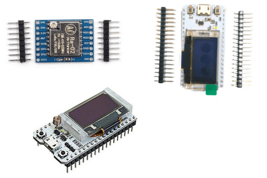
SX1278 LoRa Module
The SX1278 LoRa module is a popular choice among developers due to its low power consumption, long-range capabilities, and support for multiple frequency bands. It is based on the Semtech SX1278 chip, which is a low-power, long-range transceiver designed for use in the Industrial, Scientific, and Medical (ISM) frequency bands. The module operates in the 433MHz frequency band and has a range of up to 5 km in open space.
The SX1278 LoRa module can be easily integrated into a variety of applications, including Internet of Things (IoT) devices, smart cities, and remote monitoring systems. It supports a wide range of data rates, from 300 bps to 37.5 kbps, and has a programmable output power up to +20 dBm.
One of the key advantages of the SX1278 LoRa module is its low power consumption. It has a sleep mode that consumes only 0.1 µA of current, making it an ideal choice for battery-powered applications. The module also has a built-in temperature sensor and a low battery detector, which can be used to optimize power consumption and extend battery life.
ESP32 LoRa with Display SX1278
The ESP32 LoRa with Display SX1278 is a popular implementation of the SX1278 LoRa module. It combines the low power consumption and long-range capabilities of the SX1278 with the processing power and connectivity features of the ESP32 microcontroller. The module has a 128x64 OLED display, which can be used to display sensor readings, status messages, and other information.
The ESP32 LoRa with Display SX1278 is compatible with the Arduino IDE and can be programmed using the Arduino programming language. It has a built-in WiFi and Bluetooth connectivity, which allows it to connect to other devices and the Internet. The module also has a built-in antenna, which simplifies the integration process and reduces the overall size of the device.
One of the key features of the ESP32 LoRa with Display SX1278 is its ease of use. It comes with a preloaded firmware that can be easily customized using the Arduino IDE. The firmware includes support for LoRaWAN, a popular protocol for building large-scale IoT networks. The module can also be used with other LoRa protocols, such as LoRa-MAC, LoRa-RAW, and LoRa-P2P.
ESP32 LoRa with Display SX1276
The ESP32 LoRa with Display SX1276 is another popular implementation of the ESP32 LoRa module, but this time with the SX1276 chip. The module operates in the 868 MHz frequency band and has a range of up to 10 km in open space. Like the SX1278 module, it has a low power consumption and can be used in a variety of applications, including smart agriculture, environmental monitoring, and asset tracking.
The ESP32 LoRa with Display SX1276 has a 128x64 OLED display, which can be used to display sensor readings and other information. It also has a built-in antenna and a WiFi/Bluetooth connectivity, which allows it to connect to other devices and the Internet.
One of the key advantages of the ESP32 LoRa with Display SX1276 is its compatibility with the Arduino IDE. It can be programmed using the Arduino programming language and comes with a preloaded firmware that can be easily customized. The firmware includes support for LoRaWAN and other LoRa protocols, making it easy to build large-scale IoT networks.
In addition to its low power consumption and long-range capabilities, the ESP32 LoRa with Display SX1276 has a variety of features that make it an ideal choice for IoT applications. It has a built-in accelerometer and gyroscope, which can be used for motion sensing and orientation detection. It also has a built-in GPS module, which can be used for location tracking and geofencing.
The module can be powered by a variety of sources, including batteries, solar panels, and external power sources. It also has a deep sleep mode that consumes only 10 µA of current, making it an ideal choice for battery-powered applications.
Conclusion
The SX1278 LoRa module and the ESP32 LoRa with Display modules are two popular choices for developers looking to build IoT applications that require long-range communication and low power consumption. The SX1278 module is a versatile solution that can be easily integrated into a variety of applications, while the ESP32 LoRa with Display modules provide additional features, such as processing power, connectivity, and display capabilities.
When selecting a LoRa module, developers should consider their specific requirements, such as range, power consumption, data rate, and frequency band. They should also consider the features and capabilities of the module, such as built-in sensors, connectivity options, and compatibility with different protocols and programming languages.
Overall, LoRa technology provides an attractive alternative to traditional wireless communication technologies, such as WiFi and Bluetooth, for IoT applications that require long-range communication and low power consumption. With the availability of versatile LoRa modules, such as the SX1278 LoRa module and the ESP32 LoRa with Display modules, developers have more options than ever before to build innovative IoT solutions.
0 notes
Text
[Media] TTGO T-Beam ESP32 LoRa
TTGO T-Beam ESP32 LoRa The TTGO T-Beam is a long-range wireless capable board supporting LoRa, built around a dual-core ESP32 chip with 4MB of SPI flash onboard, providing both Wi-Fi and Bluetooth LE. The board's LoRa support comes in three different variants, operating at 433MHz, 868MHz, and 915MHz depending on region, with an included SMA antenna. Location tracking is provided by the onboard u-blox NEO-6M GPS module with ceramic antenna, and the board offers 26-pin headers with GPIO, ADC, VP/VN, DAC, touch, SPI, I2C, UART, 2דLoRa” pin, and power signals (5V/3.3V/GND). The board can be programmed using the Arduino development environment, and example code shows you how to both send and receive data via LoRa. The board also includes a battery holder for a 18650 Li-Ion cell. Repository: https://github.com/Xinyuan-LilyGO/LilyGo-LoRa-Series Buy online: 🛒 https://alii.pub/6mgzin 🛒 https://amzn.to/3Z2WUh4 #radio #lora #mesh #ESP32

0 notes
Text
Today 3/15/19
Today 3/15 Malena, Chanan, and myself (Emily) met with Zenzele, Obden, and Julia to discuss needs and options and means of researching our project. Julia and Obden had prepared an extensive and thorough presentation of the research materials and means available to us at the center and more widely in Brooklyn and NYC. Then we asked a few questions - what was the target audience? Was there something we could do to support any grant applications they were preparing or looking to prepare? Were there folks we could reach out to already who might be interested in participating or collaborating on a project? They mentioned millennials as a (relatively) underrepresented audience, suggested that our documenting our process might help with grants, and gave us a few contacts we might pursue - a baptist church in the area and Michael Gains, the president of the Tenants Association at Kingsboro houses who also works with the senior homes across the street.
Then we explained a few ideas we had had - an ongoing gallery of local artists with a skill share, projections inside of the house, sound design in the place, and the idea of the GPS map/walking tour. We were leaning toward doing something in the space of the historic houses then also something outside on the "stoop" of the newest house that faces the Kingsboro Houses.
We then had the opportunity to go out and look at the stoop and at the outdoor space available to us on May 11. Seeing the expanse of the house's siding in the back was totally inspirational - all I can see still is the whole space of the two floor building filled with projections that bridge the gap somehow between past and present. Perhaps an old scene with live streaming over top. Perhaps something totally different - research will tell. This space is visible from the Kingsboro houses across the street and is the opportunity I at least was hoping for to present something huge and eye catching and beautiful and inviting to the residents who live right across the street. We became entranced by the steps of the home and as we walked in, I could hear Malena falling in love with the house and the possibilities in terms of projection and sound design for bringing the home to life. I took extensive photographs that I'm very excited to look through in a minute - I was particularly struck by the image of the curtains and of the Kingsboro houses through the old windows of the house. It was mentioned that there is a previous resident of the home who might be able to talk with us, and this possibility seems the first route to pursue, as we're hoping to create something immediate and present in the old home.
As we were talking, Malena made a joke about H&M and about how folks nowadays don't know how to mend clothes. Obden mentioned that he was interested in doing skill work where people could learn how to sew or something - and this made me remember the element of the artist-sourced program I had liked earlier - the skill share.
So at this moment, our dream is to project onto the siding of the house to entice folks to come investigate the space, and to create an interactive projection and sound installation in the house that could stand for several days, all the while with a party going on outside on the grass where we would serve food and facilitate skill shares on some topic that allowed participants to take a physical thing home with them. We have ideas surrounding a dress that are still in the works, but perhaps we pre-film and project actors all wearing the same dress, and at the top floor of the house the dress presently exists, perhaps blowing a little on the power of an arduino?
We want to maybe depict the lost women, the “un-notable” women of the society, but are cognizant of the effects of depicting women doing “women’s work” - it’s ideas that need researching more and thinking more...
A tall order. But perhaps not beyond reach.
1 note
·
View note
Text
GPS location tracker by using NEO6M
The Neo-6M GPS module is a popular GPS module that can be used to track location. You can interface it with a microcontroller like Arduino and write a program to track and store the GPS data. The GPS module provides data in NMEA format, which you can parse to extract relevant information such as latitude, longitude, altitude, speed, etc. This information can then be displayed on an OLED display,…
View On WordPress
0 notes
Text
0 notes
Text
Introduction: Making a rocket flight computer might sound like a daunting task at first, but with the right guidance, it can be a fun and challenging project that will help you learn a lot about electronics and programming. A rocket flight computer is essentially a device that uses sensors, microcontrollers, and software to gather and process data during the flight of a rocket. This data can include altitude, velocity, temperature, and other parameters that can help you ensure a safe and successful rocket launch. In this article, we will guide you through the process of making a rocket flight computer from scratch, including the materials you need, the components you need to assemble, and the programming you need to do. We will also include a FAQs section at the end to answer some common questions about rocket flight computers. Materials: To make a rocket flight computer, you will need the following materials: - Microcontroller board: We recommend using an Arduino or a Raspberry Pi for this project, as they are easy to use and have plenty of online support and tutorials. - Sensors: You will need sensors to measure altitude, temperature, and other parameters. For altitude, you can use a barometric pressure sensor, such as the BMP280 or the BME280. For temperature, you can use a thermistor or a digital temperature sensor, such as the DS18B20. - GPS module: A GPS module will allow you to track the location and speed of your rocket during flight. - SD card module: An SD card module will allow you to store data on an SD card during flight, which you can later analyze on your computer. - Power source: You will need a power source for your flight computer. You can use a battery pack, a power bank, or a USB cable connected to your computer. - Breadboard and jumper wires: You will need a breadboard and jumper wires to connect your components together. - Case: You may want to use a case to protect your flight computer during flight. Components: Once you have gathered all the materials, you will need to assemble them into a flight computer. Here are the steps: 1. Connect the sensors: Connect the sensors to the microcontroller board using jumper wires. For the BMP280 or the BME280 sensor, connect VCC to 3.3V, GND to GND, SDA to A4, and SCL to A5. For the DS18B20 temperature sensor, connect VCC to 5V, GND to GND, and the signal pin to a digital pin on your microcontroller board. 2. Connect the GPS module: Connect the GPS module to the microcontroller board using jumper wires. Connect VCC to 3.3V, GND to GND, RX to a digital pin on your microcontroller board, and TX to another digital pin on your microcontroller board. 3. Connect the SD card module: Connect the SD card module to the microcontroller board using jumper wires. Connect VCC to 5V, GND to GND, MISO to pin 12, MOSI to pin 11, CLK to pin 13, and CS to pin 10. 4. Write the code: Once you have connected all the components, you will need to write the code for your flight computer. You can use the libraries provided by the sensors and GPS modules to read data from them, and you can use the SD card library to write data to the SD card. You will also need to create a loop that reads and processes data from the sensors and GPS module, and writes it to the SD card. Here is an example code for an Arduino flight computer (note that you may need to adjust the code for your specific components and sensors): #include #include #include #define BMP_SDA A4 #define BMP_SCL A5 #define GPS_RX 10 #define GPS_TX 11 Adafruit_BMP280 bmp; Adafruit_GPS gps(&Serial1); File dataFile; void setup() Serial.begin(9600); while (!Serial); Serial1.begin(9600); bmp.begin(0x76); SD.begin(10); dataFile = SD.open("data.log", FILE_WRITE); gps.sendCommand(PMTK_SET_NMEA_OUTPUT_RMCONLY); gps.sendCommand(PMTK_SET_NMEA_UPDATE_10HZ); gps.sendCommand(PGCMD_ANTENNA); delay(1000); void loop() float altitude = bmp.readAltitude(1013.25); float temperature = bmp.readTemperature(); char* date = gps.date;
char* time = gps.time; float latitude = gps.latitude; char* latDir = gps.lat; float longitude = gps.longitude; char* lonDir = gps.lon; float speed = gps.speed; float angle = gps.angle; float mag = gps.mag; Serial.print(altitude); Serial.print(","); Serial.print(temperature); Serial.print(","); Serial.print(date); Serial.print(","); Serial.print(time); Serial.print(","); Serial.print(latitude, 6); Serial.print(","); Serial.print(latDir); Serial.print(","); Serial.print(longitude, 6); Serial.print(","); Serial.print(lonDir); Serial.print(","); Serial.print(speed); Serial.print(","); Serial.print(angle); Serial.print(","); Serial.println(mag); dataFile.print(altitude); dataFile.print(","); dataFile.print(temperature); dataFile.print(","); dataFile.print(date); dataFile.print(","); dataFile.print(time); dataFile.print(","); dataFile.print(latitude, 6); dataFile.print(","); dataFile.print(latDir); dataFile.print(","); dataFile.print(longitude, 6); dataFile.print(","); dataFile.print(lonDir); dataFile.print(","); dataFile.print(speed); dataFile.print(","); dataFile.print(angle); dataFile.print(","); dataFile.println(mag); dataFile.flush(); delay(100); 5. Test the flight computer: Once you have written the code, you can upload it to your microcontroller board and test the flight computer. You can do this by connecting the flight computer to your computer using a USB cable, and opening the serial monitor to see the data being read from the sensors and GPS module. You should also test the SD card module to make sure it is writing data correctly. FAQs: 1. What can I do with a rocket flight computer? A rocket flight computer can help you gather data during the flight of a rocket, which can be useful for analyzing and optimizing the rocket's performance. It can also help you ensure a safe and successful rocket launch by detecting any anomalies or errors during flight. 2. Can I use a different microcontroller board for the flight computer? Yes, you can use any microcontroller board that has the required sensors and libraries. However, Arduino and Raspberry Pi are popular choices due to their low cost and ease of use. 3. How do I mount the flight computer on my rocket? You can mount the flight computer inside a protective case or container, and attach it to the rocket using tape, glue, or a mounting bracket. Make sure the flight computer is secure and well-protected during flight. Conclusion: Making a rocket flight computer can be a challenging but rewarding project that will help you learn a lot about electronics, programming, and rocketry. By following the steps outlined in this article, you can create a flight computer that will gather and process data during the flight of a rocket, and help you ensure a safe and successful rocket launch. Remember to always prioritize safety during your rocketry experiments, and have fun exploring the exciting world of rocket science! Images: [Insert images of a rocket flight computer, sensors, microcontroller board, GPS module, SD card module, and breadboard] If you have any questions or comments Please contact us on our contact page or via our Facebook page. #rocket #flight #computer
0 notes
Text
Install and use coolterm

#Install and use coolterm for free#
#Install and use coolterm for mac#
example: /Applications/CoolTermMac/Default. Download CoolTerm for Windows to monitor, troubleshoot, debug, or test serial port connections and performance CoolTerm has had 2 updates within the past 6 months. Setup the program how you like it (For me it was to the cisco specs)īrowse to the location you saved the Default connection from the previous stepĬopy and paste into the location that your CoolTerm program executes. To setup a default configuration, follow the steps below: However after a bit of searching around i found that it was possible.
#Install and use coolterm for mac#
One such serial terminal for Windows is RealTerm and for Mac is CoolTerm. A serial terminal can be used to establish a communication between a PC/Mac and other devices. The driver for CP210x can be installed on all platforms Windows, Mac and Linux. On first glance it looked as though i would have to enter these settings everytime i ran the CoolTerm program, which seemed to be a bit of a drag considering it wasn't the first thing that popped up when the program was opened. If you have Arduino IDE installed, you can just use the Serial Monitor present inside. Active X should be registered automatically. CoolTerm is a simple serial port terminal application (no terminal emulation) that is geared towards hobbyists and professionals with a need to exchange data with hardware connected to serial ports such as servo controllers, robotic kits, GPS receivers, microcontrollers, etc. Personally i liked they way that you could set up a default connection in putty with the required settings such as Baud rate, Data Bits, Parity, Stop Bits & Flow control. Realterm should be installed by an Administrator user on XP, Vista, Win7,8. Coming from a windows background i usually used SecureCRT or Putty.
#Install and use coolterm for free#
Written by Roger Meier, and avaliable for free over at his website. Download the Free Program CoolTerm, or another USB command line application. I came across a few different options but found CoolTerm to be the one for me. However, if your use of the Mintaka DUO / DUO+ / STAR data requires a. CoolTerm is freeware/donationware developed by Roger Meier, and is available for Windows / Mac / Linux devices. CoolTerm is a user-friendly terminal for serial communication with hardware that has been connected to your computer via serial ports. 99% of its use is to configure Cisco switches/routers & wireless access points. Step 3: Select the product feature and click on Install button. Next i was on the hunt to find something that i could actually use with the freshly installed adapter. So recently i finally managed to get my Aten USB to Serial adapter working with my Macbook Pro running OSX Mountain Lion.
0 notes
Photo

Carve Wind. The android app for my Carve GPS device has a small face lift. New splash screen with possibly new logo. . . . . #gadget #tech #code #programmer #programming #windsurf #sail #surf #gps #device #makersgonnamake #maker #arduino #kitesurf #electronics #coding #woodstock #capetown #nerd (at Cape Town, Western Cape) https://www.instagram.com/p/BnGJlrHFh2F/?utm_source=ig_tumblr_share&igshid=oqo161a6c7ox
#gadget#tech#code#programmer#programming#windsurf#sail#surf#gps#device#makersgonnamake#maker#arduino#kitesurf#electronics#coding#woodstock#capetown#nerd
1 note
·
View note
Text
Coolterm arduino mac

Coolterm arduino mac mac os x#
Coolterm arduino mac software download#
Coolterm arduino mac serial#
Coolterm arduino mac Pc#
Coolterm arduino mac mac os x#
The application is designed for Windows, but you can use it on Mac OS X and Linux as well. You can use this application as a terminal, to issue commands to servo controllers, robotic kits, GPS receivers and many other devices.
Coolterm arduino mac serial#
CoolTerm allows you to exchange data with devices that are connected to your computer via serial ports.
Coolterm arduino mac Pc#
The review for CoolTerm has not been completed yet, but it was tested by an editor here on a PC and a list of features has been compiled see below.Windows makes it easy to execute all sorts of actions on a computer, but it does not help you with much, when it comes to controlling external hardware.
Coolterm arduino mac software download#
Is there any free software for serial ports?ĬoolTerm is a freeware serial port terminal software download filed under network software and made available by Roger Meier for Windows. Today’s example will involve an Arduino Uno board with a HC-SR94 Ultrasonic Sensor. In this section, I will show you how we can use CoolTerm to easily monitor some sensor data in real time. What kind of microcontroller can use coolterm?Īrduino is a popular microcontroller platform that utilises serial port communication. CoolTerm is freeware/donationware developed by Roger Meier, and is available for Windows / Mac / Linux devices. Who is the creator of the coolterm terminal?ĬoolTerm is a user-friendly terminal for serial communication with hardware that has been connected to your computer via serial ports. CoolTerm is not only suitable for basic serial communication monitoring. This allows us to save our data into a convenient txt file for further analysis on our preferred platforms. In this case, we can proceed to Connection > Capture to Text/Binary File > Start…. What can I do with coolterm serial terminal? Then click into either of the two text boxes next to “Send Numbers”. To access this function, head over to the “Send” tab. The ability to send long sequences of binary, hexadecimal, or decimal values is what really sets RealTerm apart from the other terminal programs we’ve discussed. You could also write a program on your PC to receive the data and save it into a file. The simplest way would be to use a program such as puTTY in place of the Arduino Serial Monitor. How do I export data from Arduino serial monitor to a CSV or TXT file? It can be used to communicate with all kinds of devices with a serial interface, such as embedded computers, microcontrollers, modems, GPS receivers, CNC machines and more. GTKTerm is a simple, graphical serial port terminal emulator for Linux and possibly other POSIX-compliant operating systems. What is a purpose of a CoolTerm software?ĬoolTerm is a simple serial port terminal application (no terminal emulation) that is geared towards hobbyists and professionals with a need to exchange data with hardware connected to serial ports such as servo controllers, robotic kits, GPS receivers, microcontrollers. You can download it from this Sourceforge link. RealTerm is an open source software program, so it is free to use and distribute. Realterm is an engineers terminal program specially designed for capturing, controlling and debugging binary and other difficult data streams. you can write the sensor data to the serial port using serial-lib and write a small processing program that reads the data from the serial port and writes it to a file. HTTP upload to via an Ethernet shield or Ethernet Arduino. Saving data to an SD card mounted on the Arduino.
Step 6: And You Should Get Something Like This.
Step 3: Connecting to the Serial Port in CoolTerm.
CoolTerm is a serial port terminal application.
0 notes
Text
Rowe ami jukebox 200 selection stereo

#Rowe ami jukebox 200 selection stereo generator
#Rowe ami jukebox 200 selection stereo drivers
#Rowe ami jukebox 200 selection stereo skin
#Rowe ami jukebox 200 selection stereo full
Videos relevant to "Model Railway Level Crossing": PIC12F617-I/P programmed for the Model Railway Level Crossing (Source component, AUD $10.00).Mechanical diagrams and label artwork for the Railway Level Crossing (PDF Download) (Panel Artwork, Free).Model Railway Level Crossing PCB pattern (PDF download) (Free).Firmware, source code and sound recording for the Model Railway Level Crossing (Software, Free).ISD1820-based voice recording and playback module (Component, AUD $7.50).Pair of PIC12F617-I/P chips for the Model Railway Level Crossing (Programmed Microcontroller, AUD $15.00).Model Railway Level Crossing PCB (AUD $5.00).Items relevant to "Model Railway Level Crossing": A Gesture Recognition Module (March 2022).Low-noise HF-UHF Amplifiers (February 2022).El Cheapo Modules: LTDZ Spectrum Analyser (January 2022).
#Rowe ami jukebox 200 selection stereo generator
El Cheapo Modules: 35MHz-4.4GHz Signal Generator (December 2021).
El Cheapo Modules: 6GHz Digital Attenuator (November 2021).
El Cheapo Modules: 3.8GHz Digital Attenuator (October 2021).
El Cheapo Modules: USB-PD Triggers (August 2021).
El Cheapo Modules: LCR-T4 Digital Multi-Tester (February 2021)Įl Cheapo Modules: USB-PD chargers (July 2021).
El Cheapo Modules: Mini Digital AC Panel Meters (January 2021).
El Cheapo Modules: Mini Digital Volt/Amp Panel Meters (December 2020).
New w-i-d-e-b-a-n-d RTL-SDR modules, Part 2 (June 2020).
New w-i-d-e-b-a-n-d RTL-SDR modules (May 2020).
El Cheapo modules: 8-channel USB Logic Analyser (February 2020).
El Cheapo modules: “Intelligent” 8x8 RGB LED Matrix (January 2020).
Three I-O Expanders to give you more control! (November 2019).
El Cheapo Modules: AD584 Precision Voltage References (July 2019).
El Cheapo Modules: Long Range (LoRa) Transceivers (June 2019).
El Cheapo Modules: Class D amplifier modules (May 2019).
#Rowe ami jukebox 200 selection stereo skin
El Cheapo Modules 23: Galvanic Skin Response (March 2019).
#Rowe ami jukebox 200 selection stereo drivers
El Cheapo Modules 22: Stepper Motor Drivers (February 2019).El cheapo modules, part 21: stamp-sized audio player (December 2018).El cheapo modules, part 20: two tiny compass modules (November 2018).El Cheapo modules Part 19 – Arduino NFC Shield (September 2018).El Cheapo: 500MHz frequency counter and preamp (July 2018).El Cheapo Modules 17: 4GHz digital attenuator (June 2018).El Cheapo Modules 16: 35-4400MHz frequency generator (May 2018).El Cheapo Modules 14: Logarithmic RF Detector (March 2018).El Cheapo Modules 13: sensing motion and moisture (February 2018).El Cheapo Modules 12: 2.4GHz Wireless Data Modules (January 2018).El Cheapo Modules 11: Pressure/Temperature Sensors (December 2017).El Cheapo Modules Part 10: GPS receivers (October 2017).El Cheapo modules Part 9: AD9850 DDS module (September 2017).El Cheapo Modules: Li-ion & LiPo Chargers (August 2017).El Cheapo Modules, Part 7: LED Matrix displays (June 2017).El Cheapo Modules, Part 6: Direct Digital Synthesiser (April 2017).El Cheapo Modules, Part 5: LCD module with I☬ (March 2017).El Cheapo Modules from Asia - Part 4 (February 2017).El Cheapo Modules From Asia - Part 3 (January 2017).El Cheapo Modules From Asia - Part 2 (December 2016).El Cheapo Modules From Asia - Part 1 (October 2016).
#Rowe ami jukebox 200 selection stereo full
You can view 0 of the 112 pages in the full issue.įor full access, purchase the issue for $10.00 or subscribe for access to the latest issues. This is only a preview of the July 2021 issue of Silicon Chip.
Notes & Errata: Advanced GPS Computer, June 2021 Mini Arcade Pong, June 2021 Refined Full-Wave Motor Speed Controller, April 2021 USB Flexitimer, June 2018.
Vintage Radio: The Rowe AMI JAL-200 jukebox.
Serviceman's Log: I’ve repaired planes before, but never tanks.
Project: Advanced GPS Computer – Part 2.
Project: Silicon Labs-based FM/AM/SW Digital Radio.
Circuit Notebook: Adding shuffle feature to low-cost MP3 player module.
Feature: El Cheapo Modules: USB-PD chargers.
Feature: How USB Power Delivery (USB-PD) works.
Publisher's Letter: Software: too many bugs, too many updates.
0 notes